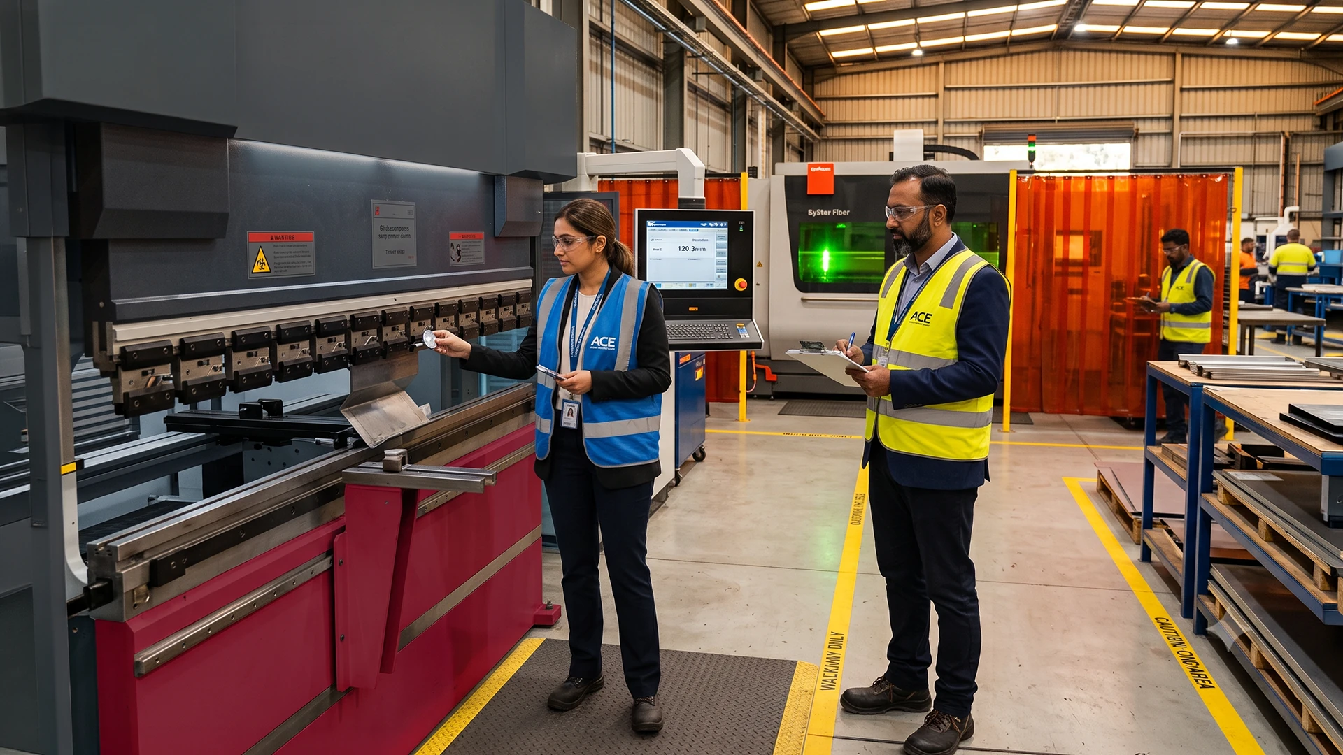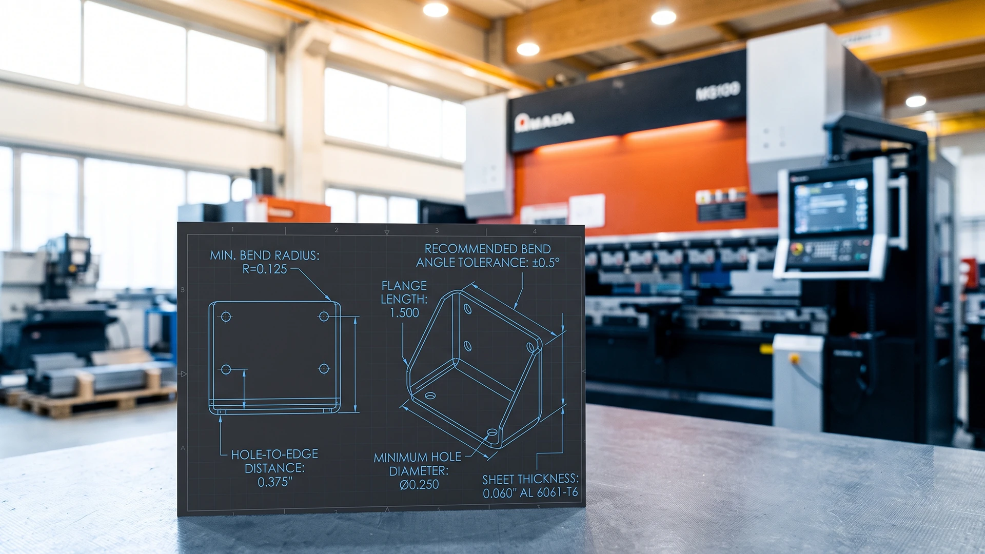
Poor sheet metal design for manufacturability is the single largest hidden cost driver in custom fabrication. A bend radius specified below material thickness forces the fabricator to use expensive tooling or accept micro-cracking. A hole placed 2 mm from a bend line distorts during forming. A tolerance tighter than the machine can hold triggers manual rework on every unit.
These errors rarely show up in the CAD model. They surface on the factory floor — as scrap, rework, tooling charges, and delayed shipments. This 12-point DFM checklist translates production engineering knowledge into actionable design rules that eliminate the most common manufacturability failures in sheet metal parts.
The 12 DFM Rules Every Sheet Metal Design Must Pass
Rule 1: Maintain Minimum Bend Radius ≥ Material Thickness
For CRCA (Cold Rolled Close Annealed) steel and mild steel up to 3 mm gauge, the inside bend radius should equal or exceed the material thickness. Going below this causes outer-fiber cracking at the bend apex.
| Material | Gauge | Minimum Inside Bend Radius |
|---|---|---|
| CRCA / Mild Steel | ≤1.5 mm | 1× thickness |
| CRCA / Mild Steel | 1.5–3.0 mm | 1× thickness |
| Stainless Steel 304 | ≤2.0 mm | 1.5× thickness |
| Aluminum 5052 | ≤3.0 mm | 1× thickness |
Exception:* Stainless steel requires a larger radius (1.5× to 2×) due to higher work-hardening rates.
Rule 2: Minimum Flange Length = 4× Material Thickness + Bend Radius
A flange shorter than this minimum cannot be gripped by the press brake die, resulting in inconsistent bend angles or the part slipping during forming. For 2 mm CRCA with a 2 mm bend radius, minimum flange = (4 × 2) + 2 = 10 mm.
Rule 3: Hole-to-Bend Distance ≥ 3× Material Thickness + Bend Radius
Holes, slots, and cutouts placed too close to a bend line deform during the bending operation. The material between the hole and the bend stretches unpredictably, producing oval holes and dimensional failures.
- For 1.5 mm mild steel with 1.5 mm bend radius: minimum distance = (3 × 1.5) + 1.5 = 6 mm from hole center to bend line
Rule 4: Hole-to-Edge Distance ≥ 2× Material Thickness
Holes punched too close to a sheet edge cause the edge to bulge outward or tear. Minimum safe distance from hole edge to part edge = 2× thickness, or the hole diameter — whichever is greater.
Rule 5: Minimum Hole Diameter ≥ Material Thickness
Punching or laser-cutting holes smaller than the material thickness creates excessive tool wear (for punching) and heat-affected zones (for laser). For 2 mm mild steel, minimum hole diameter = 2 mm.
Rule 6: Bend-to-Bend Distance ≥ 6× Material Thickness
Two parallel bends too close together create forming interference — the first flange collides with the press brake tooling when the second bend is formed. Maintain at least 6× material thickness between inside bend lines.
Rule 7: Specify Grain Direction for Critical Bends
Cold-rolled sheet has a grain direction from the rolling process. Bending perpendicular to the grain produces cleaner bends with less springback. Bending parallel to the grain increases cracking risk, especially in stainless steel.
- Best practice: Add a note on the drawing — "Bend axis perpendicular to rolling direction" — for any structural or aesthetic bend.
Rule 8: Use Standard Bend Angles When Possible
CNC press brakes with standard V-die tooling produce 90° bends most efficiently. Non-standard angles (e.g., 85°, 120°) require custom tooling or multi-step forming, adding cost and setup time.
- Preferred angles: 90°, 45°, 135°, 180° (hem)
- Avoid: angles between 170° and 179° — impossible to form without specialized coining dies
Rule 9: Design Tab-and-Slot Self-Fixturing for Welded Assemblies
Instead of specifying separate jigs and fixtures for welding alignment, design interlocking tabs and slots directly into the flat pattern. This eliminates fixture dependency, reduces welding setup time, and improves positional accuracy.
- Tab width: ≥ 1.5× material thickness
- Slot clearance: Tab width + 0.2 mm per side
Rule 10: Avoid Specifying Tighter Tolerances Than the Process Delivers
Over-tolerancing is the most expensive DFM failure because it forces the fabricator into manual measurement, selective fitting, and unit-by-unit inspection.
| Process | Achievable Tolerance |
|---|---|
| CNC fiber laser cutting | ±0.1 mm |
| CNC press brake bending (angle) | ±0.5° |
| CNC press brake bending (position) | ±0.2 mm |
| Manual MIG/TIG welding (distortion) | ±1.0–2.0 mm |
| Robotic welding | ±0.5 mm |
Design principle:* Apply tight tolerances (±0.1 mm) only to critical interfaces. Leave non-critical dimensions at ±0.5 mm or wider.
Rule 11: Optimize Flat Pattern for Nesting Efficiency
Laser cutting charges are driven by machine time and material utilization. Parts with irregular protrusions waste sheet material because they cannot nest efficiently on the cutting bed.
- Avoid unnecessary non-rectangular extensions
- Standardize part widths to common coil slit widths (e.g., 300, 400, 500 mm)
- Ask your fabricator to run a nesting simulation — a 5% improvement in material utilization compounds across production batches
Rule 12: Specify Finish Requirements on the Drawing
Surface finish specifications should appear on the engineering drawing, not in a separate email discovered after production has started.
- Powder coating: Call out color (RAL number), gloss level (matte/semi-gloss/high-gloss), and DFT (typically 60–80 microns)
- Masking: Identify surfaces that must remain bare for grounding, welding, or subsequent assembly
- Texture: Specify if a specific texture (e.g., wrinkle, sandblast) is required — these need dedicated powder formulations
The Cost Impact of DFM Failures
The cost of correcting a design error escalates at each stage:
| Stage | Cost to Correct |
|---|---|
| During CAD design | Negligible (5 minutes of design time) |
| After flat pattern release | ½ day engineering review + re-nesting |
| During first-article production | Scrap material + machine downtime + re-setup |
| After batch production (field failure) | Full recall cost + warranty liability |
A single DFM review against this checklist before releasing drawings to fabrication typically saves 10–25% of total project cost by eliminating rework, scrap, and engineering change orders.
Frequently Asked Questions
1. What is DFM in sheet metal fabrication?
Design for Manufacturability (DFM) is the practice of designing sheet metal parts so they can be fabricated efficiently — minimizing tooling, reducing scrap, and avoiding production bottlenecks. A DFM-compliant design considers bend radii, hole clearances, tolerance achievability, and material utilization before the part reaches the factory floor.
2. What is the standard bend radius for sheet metal?
For mild steel and CRCA up to 3 mm gauge, the standard minimum inside bend radius equals the material thickness (1T). Stainless steel 304 requires 1.5T to 2T due to higher work-hardening. Aluminum 5052 can achieve 1T bends.
3. How close can a hole be to a bend in sheet metal?
The minimum distance from a hole center to a bend line should be at least 3× the material thickness plus the bend radius. For 1.5 mm mild steel with a 1.5 mm bend radius, maintain at least 6 mm clearance.
4. Does grain direction matter for sheet metal bending?
Yes. Bending perpendicular to the rolling grain direction produces cleaner, stronger bends with less springback. Bending parallel to the grain — especially in stainless steel — increases the risk of micro-cracking on the outer bend surface.
Get a DFM Review Before Production
Sameta's production engineering team reviews every incoming design for manufacturability before cutting the first sheet — flagging bend interference, tolerance conflicts, and nesting inefficiencies at no additional charge. Our integrated facility handles laser cutting, CNC bending, robotic welding, and powder coating under one roof, eliminating the inter-vendor tolerance stacking that causes most assembly failures.