Under-specifying sheet metal fabrication tolerances causes parts that fail at assembly. Over-specifying them forces fabricators into manual rework on every unit, doubling your cost without improving functional performance. The tolerance specification on your RFP drawing is the single most consequential line item that determines whether you receive production-ready parts or a shipment of expensive scrap.
This guide provides the achievable tolerance ranges for every major sheet metal fabrication process — laser cutting, CNC bending, welding, and powder coating — so procurement teams can write RFP specifications that are tight enough for function and realistic enough for production.
Process-by-Process Tolerance Reference Table
The following tolerances represent achievable ranges on modern CNC-controlled equipment operated by qualified technicians. These are production tolerances — meaning they can be held consistently across batch runs, not just on a single prototype.
| Fabrication Process | Achievable Tolerance | Controlling Factors |
|---|---|---|
| CNC Fiber Laser Cutting | ±0.1 mm | Laser focus calibration, sheet flatness, assist gas pressure |
| CNC Plasma Cutting | ±0.5 – 1.0 mm | Arc wander, kerf width variation, material thickness |
| Waterjet Cutting | ±0.1 – 0.2 mm | Abrasive flow rate, cutting speed, material hardness |
| CNC Press Brake Bending (angle) | ±0.5° | Die wear, material springback, backgauge repeatability |
| CNC Press Brake Bending (position) | ±0.2 mm | Backgauge CNC accuracy, material grain consistency |
| CNC Punching / Turret Press | ±0.1 mm | Tool sharpness, sheet registration accuracy |
| Manual MIG Welding (distortion) | ±1.0 – 2.0 mm | Heat input, fixture rigidity, welder skill |
| Robotic MIG/TIG Welding | ±0.5 mm | Programmed path accuracy, fixture consistency |
| Powder Coating DFT (Dry Film Thickness) | 60 – 80 microns | Gun-to-part distance, line speed, powder charge |
| Overall Assembly (multi-process) | ±0.5 – 1.5 mm | Tolerance stacking across sequential operations |
> Critical insight: The tightest tolerance in the table is meaningless if tolerance stacking across sequential processes is not managed. A part that is laser-cut to ±0.1 mm, bent to ±0.2 mm position, and welded into an assembly carries a cumulative worst-case stack of ±0.8 mm or more at the final interface.
How to Specify Tolerances in Your RFP Without Overpaying
1. Apply Tiered Tolerancing
Not every dimension on a sheet metal part is functionally critical. Applying ±0.1 mm to all 47 dimensions on a drawing forces the fabricator to inspect and potentially rework every feature — multiplying cost by 3–5×.
Instead, use tiered tolerance classes:
| Tolerance Class | Range | When to Apply |
|---|---|---|
| Critical | ±0.1 mm | Mating surfaces, fastener hole patterns, locating features |
| Standard | ±0.5 mm | General dimensions, non-interface edges, fold lines |
| Reference | ±1.0 mm | Overall envelope dimensions, non-functional features |
2. Specify Material Before Tolerances
Tolerance achievability depends on the material. Stainless steel 304 has higher springback than mild steel, requiring tighter process control and potentially wider tolerance allowances for the same bending operation.
- CRCA / Mild Steel: Most forgiving — standard tolerances achievable on all processes
- Stainless Steel 304/316: Higher springback (2–5° additional) — specify final angle after springback compensation, not the die angle
- Aluminum 5052/6061: Low springback but prone to surface marking from die contact — may require protective film during forming
3. Reference Industry Standards in Your RFP
Instead of inventing custom tolerance tables, reference established standards:
- Cutting: ISO 2768-mK (medium–close) for general sheet metal dimensions
- Welding: AWS D1.1 (Structural Welding — Steel) for weld quality, profile, and dimensional conformance
- Finishing: ASTM B117 for salt spray corrosion testing; ASTM D3359 for coating adhesion (cross-hatch)
- Inspection: ISO 10012 or equivalent for measurement system validation
The 5 Most Expensive Tolerance Specification Mistakes
Mistake 1: Specifying ±0.1 mm on a manually welded assembly Manual welding introduces 1.0–2.0 mm of thermal distortion. Demanding ±0.1 mm on a welded assembly means every unit goes through post-weld straightening and CMM verification — a 3× cost multiplier. Solution: Design the assembly so that critical interfaces are machined post-weld, or switch to robotic welding (±0.5 mm).
Mistake 2: Not specifying a measurement datum If the drawing says "200 ±0.5 mm" but does not define from where, the fabricator measures from one edge while your receiving inspector measures from another. Result: good parts rejected on receipt. Solution: Define GD&T datums (A, B, C) on the drawing.
Mistake 3: Tolerancing bent features from the flat pattern A dimension measured on the flat pattern does not translate directly to the formed part because of bend deduction (the material shortens at the bend). Solution: Tolerance the formed-state dimension. Let the fabricator's CAM software calculate the flat pattern.
Mistake 4: Ignoring powder coating thickness in tolerance stack Powder coating adds 60–80 microns (0.06–0.08 mm) per surface. A tight-tolerance mating feature that fits perfectly in bare metal may no longer fit after coating. Solution: Specify masking on critical mating surfaces, or account for 0.15 mm total buildup (both sides) in your assembly clearance.
Mistake 5: Specifying angular tolerance in degrees when you mean positional "90° ±0.5°" controls the bend angle. But if what you actually need is for the flange tip to land within ±0.3 mm of a specific position, specify a positional tolerance. A 100 mm flange at 90° ±0.5° has a tip position variance of ±0.87 mm — which may exceed your positional requirement.
Inspection and Documentation You Should Request
For critical production runs, require the following inspection documentation with each shipment:
- First Article Inspection Report (FAIR): Dimensional measurements of every critical feature on the first production unit, typically per AS9102 format
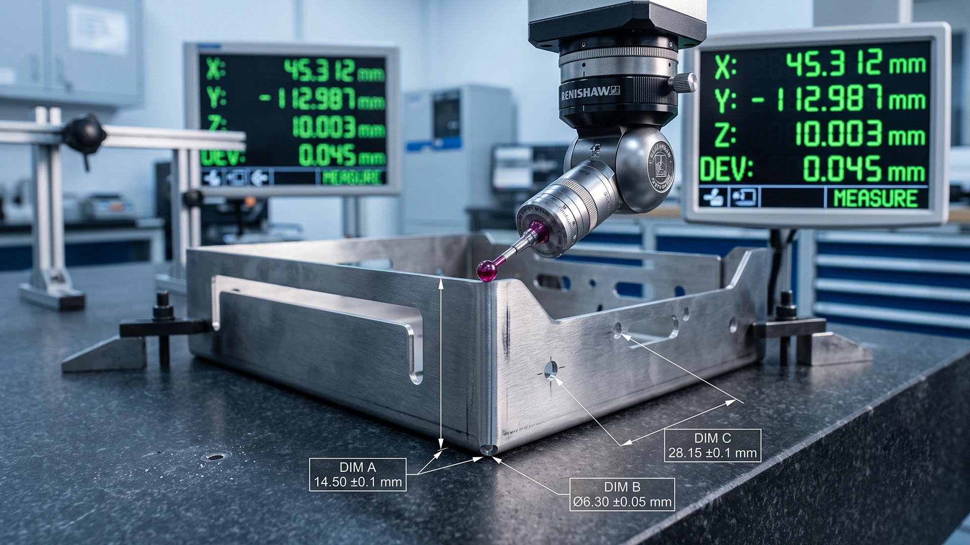
- CMM Inspection Report: Coordinate Measuring Machine data for complex 3D assemblies
- Powder Coating DFT Report: Dry film thickness readings at 5+ specified measurement points per part
- Salt Spray Test Certificate: ASTM B117 test results with hours-to-first-corrosion data
- Weld Inspection Report: Visual and dimensional per AWS D1.1, supplemented by dye penetrant or radiographic inspection where specified
- Material Test Certificates (MTCs): Mill certificates tracing raw material chemistry and mechanical properties to the source rolling mill
Frequently Asked Questions
1. What is the standard tolerance for sheet metal fabrication?
General commercial tolerance for sheet metal fabrication follows ISO 2768-m (medium class), which allows ±0.5 mm for dimensions up to 120 mm. CNC fiber laser cutting can achieve ±0.1 mm, and CNC press brake bending holds ±0.5° angle and ±0.2 mm positional accuracy.
2. How tight can laser cutting tolerances be?
CNC fiber laser cutting on modern machines achieves ±0.1 mm cutting tolerance for mild steel, CRCA, and stainless steel up to 12 mm thickness. Thicker materials and reflective metals (copper, brass) may require wider tolerances.
3. What tolerance should I specify for welded sheet metal assemblies?
For manually welded assemblies, specify ±1.0–2.0 mm to account for thermal distortion. Robotic welding reduces this to ±0.5 mm. If tighter positional accuracy is needed at weld interfaces, design post-weld machining operations into the process plan.
4. Does powder coating affect part tolerances?
Yes. Powder coating adds 60–80 microns (0.06–0.08 mm) per coated surface. For mating features, specify masking to keep critical surfaces bare, or add 0.15 mm clearance to both sides of the assembly interface.
Get Tolerance-Certified Production Runs
Sameta Metal Pro's production floor holds ±0.1 mm on CNC fiber laser cutting, ±0.5° on multi-axis press brakes, and welds to AWS D1.1 — verified by CMM inspection and documented with full dimensional reports for every production batch. From first-article qualification to volume production, every part ships with traceability from raw material mill certificate to final coating DFT.